About Monkey 2 › Forums › Monkey 2 Programming Help › mojo3d:Not understanding Texcoord on cube of quads
This topic contains 1 reply, has 2 voices, and was last updated by ![]() Mark Sibly
Mark Sibly 1 year ago.
-
AuthorPosts
-
March 23, 2018 at 6:52 pm #14115
I have a hard time understanding how to texture a mesh cube. I have been at it for hours now. I have been able to get a few sides of a cube to be textured correctly(I think) but other sides do not seem to get set correctly.
There is also texcoord1 and this seems to do not do anything. I have been at it with remapping the vertices but no succes yet.
I have created the code below from code collected from this forum. Texturing and creating a quad.
Monkey123456789101112131415161718192021222324252627282930313233343536373839404142434445464748495051525354555657585960616263646566676869707172737475767778798081828384858687888990919293949596979899100101102103104105106107108109110111112113114115116117118119120121122123124125126127128129130131132133134135136137138139140141142143144145146147148149150151152153154155156157158159160161162163164165166167168169170171172173174175176177178179180181182183184185186187188189190191192193194195#Import "<std>"#Import "<mojo>"#Import "<mojo3d>"Using std..Using mojo..Using mojo3d..Class MyWindow Extends WindowField _scene:SceneField _camera:CameraField _light:LightField _model:ModelField _rectCanvas:CanvasField _rectImage:ImageMethod New()'get scene'_scene=Scene.GetCurrent()'create camera'_camera=New Camera_camera.Near=.1_camera.Far=100_camera.Move( 0,0,-5 )'create light'_light=New Light_light.RotateX( 90 ) 'aim directional light downwards - 90 degrees.local mesh:=createcube()'create model for the mesh''_model.Material=New PbrMaterial( Color.Red )'_model.Material.CullMode=CullMode.None_model = New Model()_model.Mesh=mesh_model.Materials = _model.Materials.Resize(mesh.NumMaterials)Local sm:= New PbrMaterial()_rectImage=New Image( 256, 256 )_rectCanvas=New Canvas( _rectImage )sm.ColorTexture = _rectImage.Texturesm.ColorTexture.Flags = TextureFlags.FilterMipmap'sm.CullMode=CullMode.None_model.Materials[mesh.NumMaterials - 1] = smEnd MethodMethod OnRender( canvas:Canvas ) OverrideRequestRender()RenderTexture()controls()'_model.RotateY( 1 )'_model.RotateZ( -1 )_scene.Update()_scene.Render( canvas,_camera )canvas.DrawText( "cursors and wasd - Width="+Width+", Height="+Height+", FPS="+App.FPS,0,0 )If Keyboard.KeyReleased(Key.Escape) Then App.Terminate()End MethodMethod createcube:Mesh()'create cube mesh'Local vertices:=New Vertex3f[8]vertices[0].position=New Vec3f( -1, 1,-1 )'left front topvertices[1].position=New Vec3f( 1, 1,-1 )'right front topvertices[2].position=New Vec3f( 1,-1,-1 )'right front bottomvertices[3].position=New Vec3f( -1,-1,-1 )'left front bottomvertices[4].position=New Vec3f( -1, 1, 1 )'left back topvertices[5].position=New Vec3f( 1, 1, 1 )'right back topvertices[6].position=New Vec3f( 1,-1, 1 )'right back bottomvertices[7].position=New Vec3f( -1, -1, 1 )'left back bottom' Texture coordinates represent coordinates within the image, where' 0,0=top left, 1,0=top right, 1,1=bottom right, 0,1=bottom leftvertices[0].texCoord0 = New Vec2f(0,0)vertices[1].texCoord0 = New Vec2f(1,0)vertices[2].texCoord0 = New Vec2f(1,1)vertices[3].texCoord0 = New Vec2f(0,1)vertices[4].texCoord0 = New Vec2f(1,0)vertices[5].texCoord0 = New Vec2f(0,0)vertices[6].texCoord0 = New Vec2f(0,1)vertices[7].texCoord0 = New Vec2f(1,1)Local indices:=New UInt[36]'frontindices[0]=0indices[1]=1indices[2]=2indices[3]=0indices[4]=2indices[5]=3' left sideindices[6]=4indices[7]=0indices[8]=3indices[9]=4indices[10]=3indices[11]=7'back sideindices[12]=5indices[13]=4indices[14]=7indices[15]=5indices[16]=7indices[17]=6'right sideindices[18]=1indices[19]=5indices[20]=6indices[21]=1indices[22]=6indices[23]=2'top sideindices[24]=4indices[25]=5indices[26]=1indices[27]=4indices[28]=1indices[29]=0'bottom sideindices[30]=3indices[31]=2indices[32]=6indices[33]=3indices[34]=6indices[35]=7Return New Mesh( vertices,indices )End MethodMethod RenderTexture()If Not _rectCanvas Then_rectCanvas=New Canvas( _rectImage )Endif'This should be orange with white text on'But since I'm drawing something in the top left corner -'I'm just getting that top left pixel on the entire rectangle_rectCanvas.Clear( Color.Blue )_rectCanvas.Color = Color.White_rectCanvas.DrawText( "Hello World", Rnd(8,12), 8 )_rectCanvas.Color = Color.Orange_rectCanvas.DrawRect( 50, 50 , 200 ,90) 'White in the top left_rectCanvas.Flush()End MethodMethod controls()If Keyboard.KeyDown(Key.W) Then _camera.Move(0,0,.2)If Keyboard.KeyDown(Key.S) Then _camera.Move(0,0,-.2)If Keyboard.KeyDown(Key.A) Then _camera.Move(-.2,0,0)If Keyboard.KeyDown(Key.D) Then _camera.Move(.2,0,0)If Keyboard.KeyDown(Key.Up) Then _camera.Rotate(1,0,0)If Keyboard.KeyDown(Key.Down) Then _camera.Rotate(-1,0,0)If Keyboard.KeyDown(Key.Left) Then _camera.Rotate(0,1,0)If Keyboard.KeyDown(Key.Right) Then _camera.Rotate(0,-1,0)End MethodEnd ClassFunction Main()New AppInstanceNew MyWindowApp.Run()End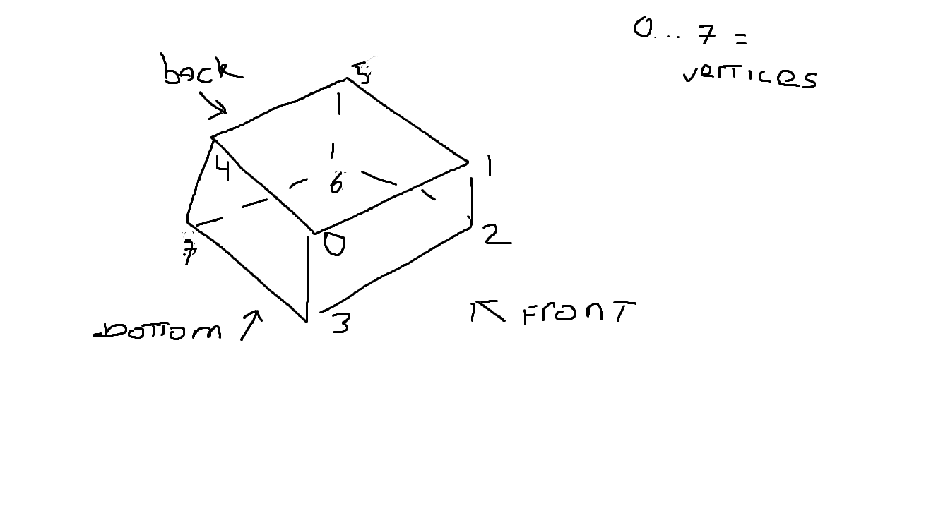 March 23, 2018 at 9:01 pm #14116
If you want unique texcoords for each face of the cube (which I’m guessing is what you’re after) you need to duplicate the ‘shared’ vertices (ie: vertices with the same position) so each vertex gets its own texcoords. This will allow vertex 0 above to have different tex coords when used in the front quad (eg: 0,0) than when used in the left quad( eg: 1,0) because it’s really 2 vertices.
This goes for any vertex attribute you want to to be different depending on the polygon it’s used in. For example, to ahieve flat-shading, vertices will have a different normal for each triangle they are used in (ie” the triangle’s normal) so a flat shaded mesh can’t have *any* shared vertices.
Anyway, this means you should end up with 24 vertices (6 faces * 4 vertices per face) altogether. This is what Mesh.CreateBox does, you might want to have a look at that…
And note that texcoord1 is not used by the built in shader.
-
AuthorPosts
You must be logged in to reply to this topic.